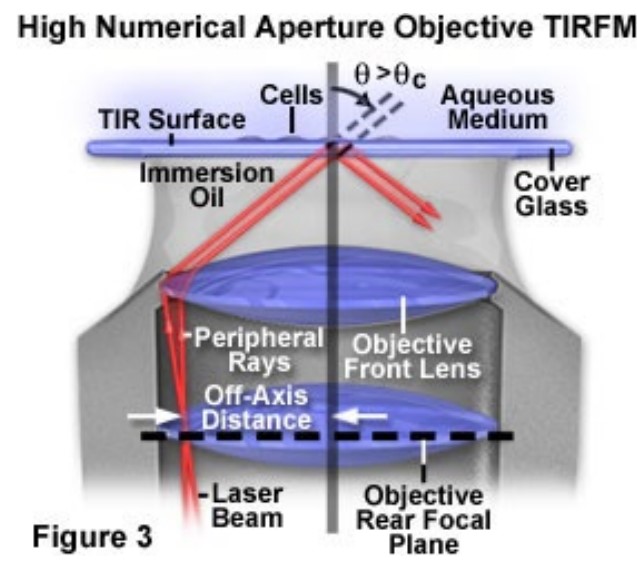
5.3 Objective-Based TIRFM
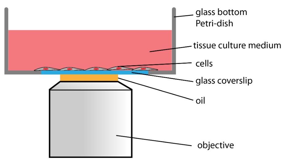
Figure 5.11: Schematic of a TIRFM
TIRFM is short for total internal reflection fluorescence microscopy.
5.3.1 Total Internal Reflection
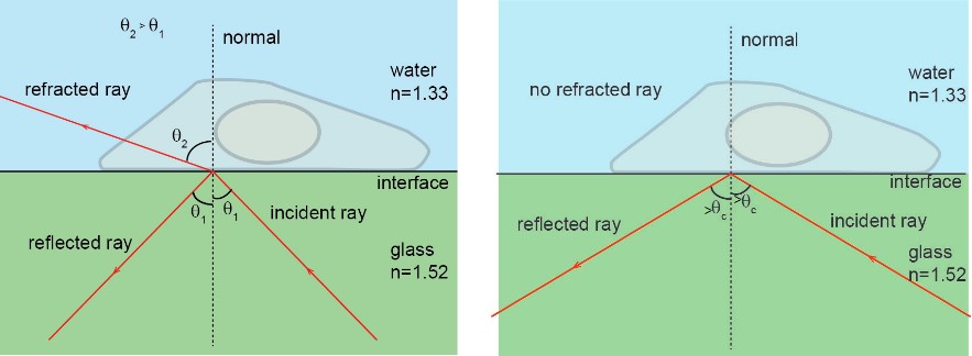
Figure 5.12: Law of Refraction in TIRFM
The law of refraction states the following in this case:
1.52×sin(θ1)=1.33×sin(θ2)
When a colliminated light beam goes from glass into water, the refractive angle θ2 is larger than the incident angle θ1. As θ1 increases, so does θ2 - the refracted light is dimmer and the reflected light stronger.
When θ1≥60∘ (i.e., the critical angle θc), the incident ray is reflected back into the glass. Otherwise, when θ2=90∘, the direction of refracted light is parallel to the interface.
5.3.2 Evanescent Field
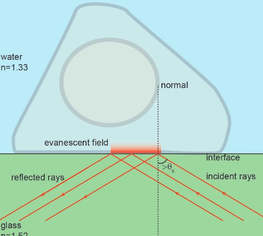
Figure 5.13: An Evanescent Field
This is a result of the total internal reflection at the glass and aqueous interface. The field is essentially a small portion of light (at about 100 to 200 nm) that illuminates a cell at the glass and aqueous solution interface.
Within this field, light intensity drops as distance from the interface increases. Only adherent cells’ plasma membranes can be observed by TIRFM.